ABSTRACT: In this piece, I chose to focus on a device that is commonly used by electrical engineers. For my first attempt, I focused mainly on how to use a multimeter. That idea was wrong and instead, I had to focus on how the multimeter function. Nonetheless, I understood the assignment and wrote a detailed piece.
Bismah Hasan
Writing For Engineering
Technical Description and Instruction
March 27 2020
MULTIMETER
DEFINITION AND PURPOSE
To be an Electrical engineer. You must know how to use a multimeter. Multimeters assist in measuring voltage, resistance, and current in any circuit. This technical description will go over the instructions on how a multimeter works.
FUNCTION
A multimeter is an electrical measuring instrument that combines several functions in one unit.
Using the probes of the Multimeter, it can measure the following:
- Current: Your multimeter’s ammeter function is used to measure the number of electrons passing a given point for a certain amount of time (current). The units in this measurement are known as amperes and excessive current can cause a circuit breaker to open.
- Resistance: The ohmmeter function measures electrical resistance which is the opposition to an electric current and its unit is ohms. An electrical circuit will have a resistance of zero or near zero ohms if it is short-circuited. When a circuit is open it has infinite resistance and no current flow.
- Voltage: The voltmeter function of your multimeter measures the electrical potential between two points in volts and is especially useful for checking whether a battery is nearly dead.
OVERVIEW AND DESCRIPTION
There are two types of multimeter: Analog and digital. In an analog multimeter, the readings are displayed using a micrometer with a moving pointer. While a digital multimeter uses a numeric display. Within the years’ digital multimeters have become more common due to its cost and precision. When probes are touched into a current of electricity, the electricity will flow through the circuits and will be measured. Electricity is then converted into voltage. Then this voltage is measured by the circuits and the output is displayed. The electricity is passed through a device called a shunt. Shunt measures resistance of the voltage that flows across the circuitry. The Multimeter also incorporates a Flash AD converter. This device uses comparators, encoders, to digitally display readings. Comparators develop inputs, the encoder converts its inputs to corresponding outputs that drive the digital display.
The digital multimeter’s operation is related to the measurement time. Apart from the basic measurement there are a number of other functions that are required and these all take time. The overall measurement time for a DMM is made up from several phases where different activities occur:
- Switch time: The switch time is the time required for the instrument to settle after the input has been switched. This includes the time after a measurement type has been changed, (for example from voltage to resistance, etc.).
- Settling time: Once the value to be measured has been applied to the input, a certain time will be required for it to settle.
- Signal measurement time: This is the basic time required to make the measurement itself. For AC measurements, the frequency of operation must be taken into account because the minimum signal measurement time is based on the minimum frequency required of the measurement. (For example, for a minimum frequency of 50 Hz, an aperture of four times the period is required, i.e. 80 ms for a 50Hz signal, or 67ms for a 60Hz signal, etc.)
- Auto-zero time: When range changes are made, it is necessary to zero the meter to ensure accuracy. Once the correct range is selected, the auto-zero is performance for that range.
- ADC calibration time: In some digital multimeters a calibration is periodically performed. (specifically where measurements are taken under automatic or computer control.)
Components And Parts
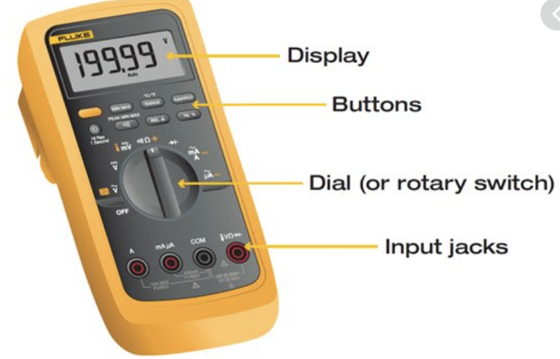
FIGURE 1
- Display: Where measurements readout can be viewed
- Buttons: for selecting different functions.
(Note: The options may vary by models)
- Dial (or Rotary Switch): For selecting primary measurement values (volts, amps, ohms)
- Input Jacks: Where the probes test leads are inserted.
More visuals


FIGURE 2 FIGURE 3
Figure 2 and Figure 3 are different models. In figure 3, the probe is visual. It shows how the test leads are inserted into the socket/ input jacks. (NOTE: the black probe is always inserted into the socket labeled ‘common’, common ground. The red probe depends on what you are measuring. If you are measuring the voltage or current. The probe should be inserted into the specific socket that you are measuring for. )

Figure 4 shows how the current is measured. When the probes are attached to the metal strips, the circuit will work. In this case, the rotor is spinning. The reading of the current will be displayed.
CONCLUSION
A multimeter can be very useful because it has many functions. The multimeter is not a complex tool to use. It comes in different colors and models. The main function is to measure current, voltage, resistance, and continuity. Some models can also identify temperature.
TIPS:
- Multimeters can be bought from any hardware stores or online (Amazon, eBay, etc)
- +/-2 accuracy is good enough
- Multimeter’s price can range from $30 to $4,000. For regular use, a cheaper one is preferred.
- Be Careful when using a red probe. If the red probe is plugged into the wrong jack, there will be a chance of a fuse blowing in your multimeter.
SAFETY
A digital multimeter presents potential safety hazards that must be considered when working with electrical measurements. Before using electrical test equipment, always refer to the user’s manual for proper operating procedures, safety precautions, and limits.
CITATION:
- https://www.fluke.com/en-us/learn/best-practices/test-tools-basics/digital-multimeters
- https://www.sciencebuddies.org/science-fair-projects/references/how-to-use-a-multimeter
- https://www.faa.gov/regulations_policies/handbooks_manuals/aircraft/media/amt_general_handbook.pdf

This entry is licensed under a Creative Commons Attribution-NonCommercial-ShareAlike 4.0 International license.